
基板クイック試作

カスタム基板試作サービス

Hardware sizing and options

Part Sizes

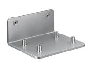
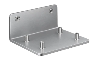
Hardware insertion permanently embeds press fit fasteners into sheet metal substrates. It requires sufficient base material thickness for reliable installation; the acceptable hole dimension is determined by the selected fastener model.

  • Min part thickness (flat):
    0.8 mm
  • Max part dimension (flat):
    Unlimited
  • Max hole diameter:
    Fastener-dependent

Hardware Installation Options · Matched to Your Needs

Secure · Permanent
PEM Fasteners
Press-fit fasteners are installed directly into sheet metal to provide durable threaded or mounting points.
  • Nuts.
  • Studs.
  • Standoffs.
  • Flush head fasteners for low profile surface conditions.
Secure · Permanent
PEM Fasteners
Press-fit fasteners are installed directly into sheet metal to provide durable threaded or mounting points.
Threaded · Versatile
Rivet Nuts
Rivet nuts create internal threads in sheet metal where access is available from only one side.
Fast · Reliable
Rivets
Rivets permanently join overlapping sheet metal components without requiring threaded holes.

Available Materials For Hardware Installation

In addition to the materials listed below, we also accept customer-supplied materials for processing.

Our Surface Finishes For Hardware Parts

With our precise hardware installation, sheet metal assemblies gain secure, reliable fastening points,
built to support efficient assembly and long-term performance.

Standard (As-Milled) (Ra 125μin)
The finish option with the quickest turnaround. Sharp edges and burrs would be removed by default. (If you need parts with sharp edges and burrs, please remark below or note on 2D drawing). Surface finish is comparable to 125 uin Ra finish.
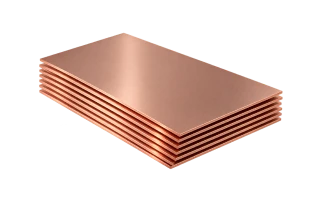
  • Copper C110
  • Stainless steel 304
  • Aluminum 5052
  • Copper 260 (Brass)

Standard (As-Milled) (Ra 125μin)

Bead blast + Anodized color

Anodized

Electrically conductive oxidation

Black oxide

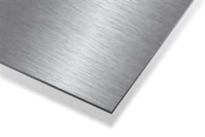
Brushed

Hardware Capability

Process Description
Min flat part thickness 0.8 mm
Max flat part dimension No hard limit for press fit installation
Max hole diameter Subject to fastener model

Hardware Installation Design Guidelines

Hardware installation adds threaded connection points, mounting features, and structural support directly to sheet metal parts. It is especially useful for thin sheet metal that is difficult to tap, applications where access to the back side is limited, and assemblies that require repeatable fastening.

This guide covers key design considerations for sheet metal parts with press-fit or self-clinching (PEM) hardware, including hardware selection, mounting hole and spacing engineering data, edge clearance, bend clearance, load direction, and production file preparation standards.


1. Hardware Options and Selection

Choosing the right hardware depends on how the finished part will be assembled and loaded.

Self-Clinching Nuts

Self-clinching nuts provide permanent internal threads in sheet metal parts. They are a practical alternative to tapping when the sheet is too thin to provide sufficient thread engagement.

  • Common Applications: Electronic enclosures, control panels, mounting brackets, equipment housings, structural sheet metal assemblies.
  • Typical Series: S/SS Series (standard steel), CLS Series (for stainless steel), SP Series (for corrosion-resistant hard stainless steel).

Self-Clinching Studs

Self-clinching studs provide a permanent threaded shaft extending from the sheet metal surface. They are useful when another component needs to be positioned over or mounted onto the sheet.

  • Typical Applications: Panel mounting, PCB mounting, electrical assemblies, brackets and supports.
  • Typical Series: FH (flush-head type), FHS (stainless steel type), TFH (thin-sheet type).

Standoffs

Standoffs create a fixed spacing between two components while providing a threaded mounting point.

  • Common Applications: PCB mounting, electronic enclosures, multi-layer assemblies, panel-to-panel mounting.
  • Typical Series: BSO (thru-hole threaded), SOO (blind threaded), CSOS (concealed-head type).

Flush Hardware

Flush or low-profile hardware is used when the installed fastener needs to remain close to or completely level with the sheet surface. Note that the final installed height varies depending on hardware type and sheet material. Always check specific hardware specifications before finalizing the design.


2. Core Design Rules and Industry Engineering Reference Data

Before laying out mounting holes, general Design for Manufacturability (DFM) rules should be combined with fastener catalogs (such as PEM standards).

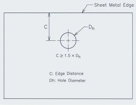
Minimum Edge Distance (Center-to-Edge Distance)

Hardware installed too close to an edge can weaken the sheet around the mounting point and cause the sheet edge to bulge or deform during installation or under load.

Engineering Rules of Thumb:

  • Rule Formula: Distance from the mounting hole center to the nearest edge C ≥ 1.5 × Dh (where Dh is the mounting hole diameter).
  • Standard Recommendation: Check "Min. Distance to Edge" in PEM catalogs. For high-load or thin-sheet applications, C ≥ 2.0 × Dh is recommended.

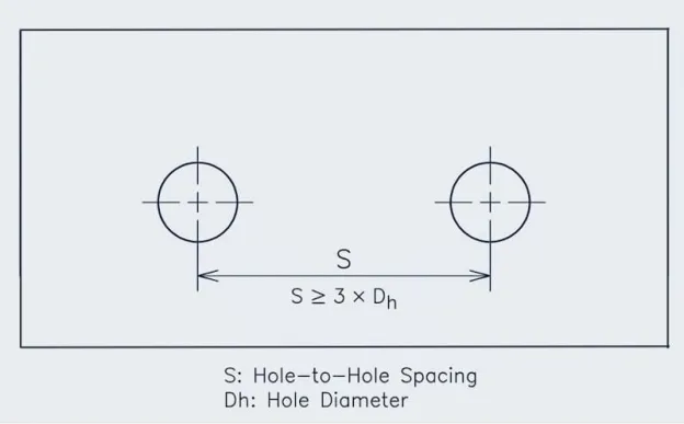
Minimum Hole-to-Hole Spacing

Adjacent hardware holes positioned too closely can cause cumulative stress deformation and weaken the sheet metal between holes.

  • Identical Hardware: Recommended center-to-center distance S ≥ 3 × Dh.
  • Different Hardware Types: Follow the larger clearance requirement and ensure installation tooling envelopes do not intersect (installation anvil diameter is typically 3-5mm larger than the hole).

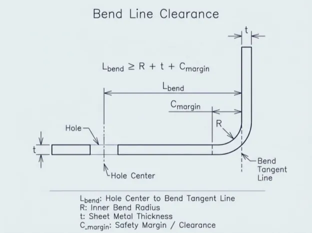
Bend Line Clearance

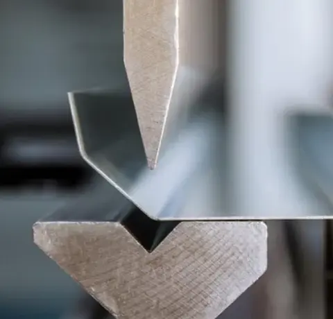
Bending creates a plastic deformation zone (bend allowance area) around the bend. Installing hardware inside or too close to this area can cause tooling interference during forming or distort the mounting hole.

Clearance Formula (Hole center to bend tangent line):

L_bend ≥ R + t + C_margin

Where R is inner bend radius, t is sheet thickness, and C_margin is safety margin (typically 1.5 to 2 times fastener flange radius, or maintaining center distance to bend line at 2t + R + 3mm or greater).


3. Load Direction and Material Compatibility

Load Direction Principle (Push-out vs. Pull-out)

Self-clinching fasteners rely on knurling and clinician grooves pressed into sheet metal for cold-flow bonding, resulting in significant differences in retention strength along different axes.

  • Nuts: Applied load must pull the nut into the sheet metal (Push-out force direction). Never apply bolt tension that directly pulls the nut out of the sheet (Pull-out force).
  • Studs: Tightening force should press the stud head firmly against the sheet surface, avoiding direct axial tension pulling the stud out from the back.

Sheet Hardness and Material Matching

Successful clinch insertion requires the fastener material to be harder than the base sheet metal so that the knurled teeth can cold-extrude into the sheet.

  • Aluminum Alloys (e.g., 5052-H32 / 6061-T6): Compatible with carbon steel (S series) or stainless steel (CLS series) fasteners. Recommended sheet hardness: HRB 50 max.
  • Cold-Rolled Steel / Galvanized Steel (SPCC/SECC): Use carbon steel (S series) or hardened stainless steel fasteners. Recommended sheet hardness: HRB 80 max.
  • Stainless Steel (e.g., 304 / 316): Hardened stainless steel fasteners (such as PEM SP series) must be used. Standard CLS stainless fasteners cannot extrude into 304 sheets. Recommended sheet hardness: HRB 88/90 max.


4. Surface Finishing and Installation Sequence

Surface treatments (powder coating, plating, anodizing) significantly affect hardware installation and should follow these engineering guidelines:


5. File Preparation Requirements (CAD/DFM)

2D DXF/DWG Files:

  • Maintain 1:1 scale, remove duplicate lines, construction geometry, and open contours.
  • Draw hardware mounting holes directly at the manufacturer's recommended standard diameter (Dh) without manual scaling.

3D STEP/STP/IGES Models:

  • Cloud Manufacturing Platforms (e.g., SCS, Xometry): Remove 3D hardware fastener models from exported STEP files, leaving only exact mounting holes to prevent automated DFM algorithms from misinterpreting fasteners as complex CNC milling features.
  • Traditional Engineering Drawings: Call out fastener BOM part numbers, specifications (e.g., PEM S-M4-1), and installation faces on assembly drawings.


6. Hardware Installation Design Checklist

  • Hardware type and thread size selected, with sheet hardness verified below fastener hardness limits (e.g., SP series for stainless steel).
  • Mounting hole size matches specifications, with edge distance C ≥ 1.5 × Dh (≥ 6.4 mm recommended).
  • Hole center to bend tangent line distance meets L_bend ≥ 2t + R + 3mm.
  • Load direction verified to pull hardware into sheet (Push-out direction) rather than pulling it out.
  • Installation area is accessible by tooling, free from interfering deep pockets, tight flanges, or narrow channels.
  • Insertion sequence coordinated with powder coating/anodizing/plating processes.
  • 3D STEP files prepared with hardware solids removed, leaving accurate mounting hole geometry.

Customer Reviews

Frequently Asked Questions

What types of hardware can be installed?

Common options include PEM nuts, studs, standoffs, rivet nuts, captive fasteners, and other hardware designed for sheet metal assemblies.

Can hardware be installed in thin sheet metal?

Yes. Press-fit fasteners, rivet nuts, and other specialized hardware can provide reliable fastening points in thin sheet metal where conventional tapped holes may not be suitable.

How do I specify hardware installation requirements?

Provide the hardware part number or type, installation location, material and thickness of the sheet, and any required orientation or installation specifications.

Why use installed hardware instead of conventional fasteners?

Installed hardware can provide secure attachment points while simplifying assembly and reducing the need for loose nuts, bolts, or additional components.

Can hardware be installed before shipping?

Yes. Hardware can be installed during production so finished parts arrive ready for final assembly.

Your files are in safe hands with us.
Start producing your project right away.

Get in touch with our team. Call us directly on. Or email us at 3dcnc@pcbway.com

Get instant quote

Full manufacturing capability at your fingertips