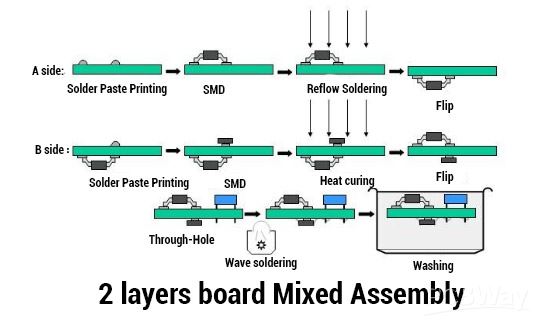
Mixed Assembly PCB, which combines surface mount technology (SMT) and through-hole technology (THT).It combined advantages of both mounting technologies.Most of the applications include SMD and throug-hole components.
What are the mixed assembly advantages?
Over a single SMT or THT design, mixed assembly PCBS have the following advantages:
Installation and rework with 100% X-ray inspection
Higher reliability: Mixed assembly technology can improve PCB reliability as it combines the advantages of both SMT and THT technologies, providing higher quality and performance. For example, SMT technology can provide higher precision and speed, while THT technology can provide greater durability and reliability
Lightweight
Increased stress-tolerance
High precision
Greater component selection: Certain components may be only available for installation through THT technology, while others may be more suited to SMT technology. Mixed assembly technology offers a greater selection of components as it allows for the use of both THT and SMT technologies to install different types of components
Increased flexibility: Mixed assembly PCBs offer greater flexibility as they can adapt to different design requirements and functional needs. This makes mixed assembly PCBs suitable for a wide range of applications, including industrial control, medical equipment, and automotive electronics
Higher performance: Mixed assembly PCBs can provide higher performance as they can combine different types of components, offering a broader range of functions. This makes mixed assembly PCBs suitable for various applications, including high-speed signal processing, power electronics, and RF applications
Higher production efficiency: Mixed assembly PCB production can be automated, leading to higher production efficiency and lower costs. It also can increase PCB manufacturing and assembly speed

DFA Evaluation for a mixed assembly
DFA( Design for Assembly) can come up with problems that may occur before the actual assembly process. Without appropriate planning, the assembly will likely not meet the actual design requirements. However, different from DFA, DFM (Design for Manufacture ) does not consider the difficulties that may appearwhen assembly, once the DFM is finished, there is only a bare board for us to assemble. Before assembly, we should take the following factors into account:
What types of components are used
Automated placement or manual placement
Design rules for placement of components
What types of components are used
During the PCBA, two technologies of SMT and THT will be used, which are suitable for different components. SMT features high precision, light weight and automatic installation while THT can provide sturdy connection and high-stress tolerance. To take full advantage of their respective virtues, it is a good choice to use them on one board.
SMT and THT each have their own corresponding welding method: reflow soldering for surface-mountedcomponents and wave soldering/hand soldering for through-hole components.
Automated placement or manual placement
The subsequent stage involves selecting the most suitable method of component placement. Here are the benefits and drawbacks of automatic placement.
Benefits of automatic placement:
Drawbacks of automatic placement:
Not suitable for processing low volumes
Inadequate precision during component placement
Issues may arise with component leads
When choosing a placement method,the above disadvantages should be considered. For smaller assembly batches, the cost of setting up automatic placement will be high. Taking this into account, choosing manual placement is the best option.
Design rules for component placement
The following requirements should be met when placing components:
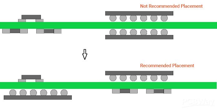
If possible, try to keep all components on same side.
If it is not possible to adhere to the aforementioned conditions, attempt to position the SMT chip components on the underside of the board.
It is crucial to avoid facing two BGA components towards each other at any cost.

It is advisable to maintain a reasonable distance between through-hole devices and BGA devices during placement.

It is essential to carefully consider the distribution of weight during component placement. Avoid placing heavy or large components near the edges of the PCB, as this can cause the board to bend.
Whenever possible, attempt to use components with the same package size during placement. Although it may not always be feasible, this practice can greatly streamline the assembly process.
Considering these aspects, mixed assembly design can be effectively implemented. Mixed assembly definitely has advantages over selecting a specific mounting technology alone.
Last but not least,PCBway provides advanced PCB manufacturing and PCB assembly services to customers around the world.Wecome to place an order.
More information check here:
PCB Assembly Instant Quote


