


8, 16, 24, 32 KB RAM internal expansion for Commodore VIC-20 + BASIC EPROM adapter
This is a tested and working project. Images taken from the real project.
This board allows to add 8 KB, 16 KB, 24 KB or 32 KB to your unexpanded VIC-20. As plus feature, it comes with an adapter that permits to replace the original BASIC ROM with a 2764 EPROM.
Requirements:
The board is installed in the BASIC ROM socket. If you BASIC ROM is soldered on the board, you need to remove it and replace it with a 24-pins socket.
Required parts (for 32 Kb full expansion):
- 4x 6264 8KB SRAM DIP ICs. Note: you need one chip every 8 KB; if you don't want a full RAM expansion, just put how many RAM chips you want.
- 5x 28 pin DIL sockets large profile. Note: you can solder the RAM chips directly on the board, avoiding the use of 4x sockets; however the use of the socket is highly recommended.
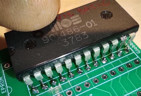
- 2764 EPROM programmed with the BASIC ROM image - get it at this address: http://www.zimmers.net/anonftp/pub/cbm/firmware/computers/vic20/basic.901486-01.bin
- 2x 12 pin male header (thin, rounded pins should be used in order to avoid any damage to the BASIC socket)
- Five wires, about 20-25 cm (better result using a ribbon cable)
NOTE: The board is intended for replacing the original BASIC ROM with a 2764 EPROM; however if, for some reason, you want to use the original BASIC ROM, you can solder the BASIC ROM on the board (instructions below). However it's highly recommended you use an EPROM. Commodore ROMs are quite prone to fail nowadays.
Building instructions:

Insert the two headers in a socket (to keep them aligned) and insert them from the bottom side of the PCB. Solder both headers.
-----------------------------------------------------------------------------------------------------\
The following step is optional and not recommended;
it is intended to allow the use of the original BASIC ROM
instead of the 2764 EPROM
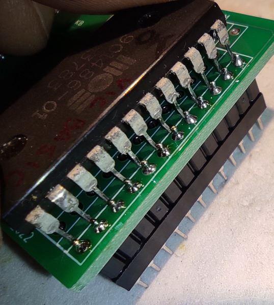
Solder the BASIC ROM chip to the upper side of the headers
Be sure the notch on the chip is aligned with the notch drawn on the PCB.
Note: In the next step you should not solder the 2764 EPROM socket
(there's no way you can solder it, actually)
NOTE: it should work but it's an untested configuration. Your own risk.
(or you can use a female+male header instead of the male header in the picture)
-----------------------------------------------------------------------------------------------------/

Solder the five sockets on the board.
Solder the five wires into the five holes like in the picture (note: the orange wire is barely visible in the picture. It's soldered into the hole labelled "6502 #34" between the two sockets on the left; the solder joint is covered by the red wire in the picture).
A ribbon cable is preferable, but any wire can be used for that purpose.
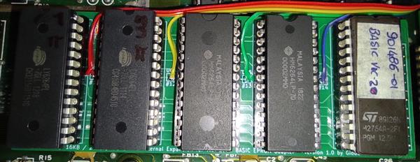
Insert the EPROM chip into the EPROM socket (the rightmost one); insert the four RAM chips into the RAM sockets (see below for different RAM configs). Plug the board in the BASIC socket of the VIC-20 board.
Note: you can glue a piece of foam on some of the 74xxx chips behind the board to keep the board leveled.
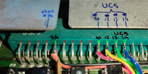
Time to connect the five wires to the VIC-20 board. The simplest way to do that is to solder the wires to the back of the cartridge connector.
Counting from left, the 5th pin (just as reference; it is the pin #18 of the cartridge port, according with the VIC-20 manual) is connected to the pin #34 of the 6502 microprocessor. Solder the wire connected to the hole "6502 #34" of the expansion board (the orange wire in the pictures).
The 10th pin from left (pin #13 of the cartridge port, according with the VIC-20 manual) is connected to UC5 pin #10. Solder the wire connected to the hole "UC5 pin #10" on the expansion board.
Using the same rule, solder the remaining wires. In case of doubts, see the above pictures: they should be quite self-explaining).
The expansion is now connected and ready to be tested. However it's quite important to double check every connection before to fire up the computer!
NOTE: IT TAKES ABOUT 5 SECONDS TO BOOT
The normal boot time for the unexpanded VIC-20 is about 2 seconds, but with a full RAM config it takes a little bit more. Please have some patience!
NOTE ABOUT RAM CONFIG:
Any configuration from 0 kB to 32 kB can be chosen simply inserting or removing the RAM chips. However, the board must to be populated from right to left. Note there's a label behind every socket - 8k, 16k, 24k, 32k:
- For 0 kB RAM remove all the RAM chip.
- For 8 kB RAM just put the 8k RAM chip.
- For 16 kB RAM put the 8k and the 16k RAM chips.
- For 24 kB RAM put the 8k, the 16k and the 24k RAM chips.
- For 32 kB RAM put all the four RAM chips.
NOTE: THE MAXIMUM AMOUNT OF VISIBLE (ADDRESSABLE) RAM IN BASIC MODE IS
28159 BYTES FREE.

IT MEANS THE BOOT SCREEN WILL NEVER SHOW MORE THAN THE ABOVE AMOUNT OF MEMORY, EVEN WITH THE FULL 32 KB RAM EXPANSION. THE FULL EXPANSION CAN BE ADDRESSED ONLY BY MACHINE LANGUAGE CODE PROGRAMS.
If you planned to use the expansion board with BASIC programs only, the fourth RAM chip ("32k" label) is totally useless.
8, 16, 24, 32 KB RAM internal expansion for Commodore VIC-20 + BASIC EPROM adapter
*PCBWay community is a shared platform and we are not responsible for any design issues.


- Comments(5)
- Likes(6)
More by Giovanni giobbi
-
 Easiest Commodore VIC-20 Characters ROM adapter
This is a tested and working project.No waste of big EPROMs, no jumpers, no configurations, no SMD. ...
Easiest Commodore VIC-20 Characters ROM adapter
This is a tested and working project.No waste of big EPROMs, no jumpers, no configurations, no SMD. ...
-
 8, 16, 24, 32 KB RAM internal expansion for Commodore VIC-20 + BASIC EPROM adapter
This is a tested and working project. Images taken from the real project.This board allows to add 8 ...
8, 16, 24, 32 KB RAM internal expansion for Commodore VIC-20 + BASIC EPROM adapter
This is a tested and working project. Images taken from the real project.This board allows to add 8 ...
-
 ROM 2364 - (E)EPROM 2764/27C64/28C64 Adapter for Commodore VIC-20, C=64, CBM disk drive 8050, 8250...
PROJECT TESTED AND WORKING IN CBM 8050 disk drive, CBM 8250 disk drive, Commodore 1541 disk drive, C...
ROM 2364 - (E)EPROM 2764/27C64/28C64 Adapter for Commodore VIC-20, C=64, CBM disk drive 8050, 8250...
PROJECT TESTED AND WORKING IN CBM 8050 disk drive, CBM 8250 disk drive, Commodore 1541 disk drive, C...
-
 Easiest Commodore 64 Characters ROM adapter
Easiest Commodore 64 Char ROM adapterThis is a tested and working project.No waste of big EPROMs, n...
Easiest Commodore 64 Characters ROM adapter
Easiest Commodore 64 Char ROM adapterThis is a tested and working project.No waste of big EPROMs, n...
-
 Commodore PET - 2332 ROM to 2732 EPROM adapter
This is a tested and working projectThis adapter is intended for replacing the original 2332 BASIC a...
Commodore PET - 2332 ROM to 2732 EPROM adapter
This is a tested and working projectThis adapter is intended for replacing the original 2332 BASIC a...
-
 Commodore Floppy Drive 1541 Adapter: use the Commodore 1541 drive as PET floppy drive (1541 to IEEE488)
The drives for the Commodore PET computers are quite scarce, unreliable, bulky and expensive and use...
Commodore Floppy Drive 1541 Adapter: use the Commodore 1541 drive as PET floppy drive (1541 to IEEE488)
The drives for the Commodore PET computers are quite scarce, unreliable, bulky and expensive and use...
-
 Commodore RAM and ROM replacement board
Fix any RAM or main ROM issue on your Commodore equipment Expand your RAM up to 32 KBProject tested ...
Commodore RAM and ROM replacement board
Fix any RAM or main ROM issue on your Commodore equipment Expand your RAM up to 32 KBProject tested ...
-
 Replacement for Commodore 6540 ROMs (PET 2001 early version)
PROJECT TESTED - WORKING FINE ON MY 1977 COMMODORE PETDrop-in replacement for the nowadays impossibl...
Replacement for Commodore 6540 ROMs (PET 2001 early version)
PROJECT TESTED - WORKING FINE ON MY 1977 COMMODORE PETDrop-in replacement for the nowadays impossibl...
-
IoT Indoor system with ESP32 to monitor Temperature, Humidity, Pressure, and Air Quality
269 0 1 -
Naruto Multi-color PCB printed with UV technology
112 2 1 -
-
-
-


