Summary: Here we will focus on type two of the clipper circuits, the negative clipper circuit that forms a significant use in the design of power electronic systems.
Part one of the Clipper Circuits briefed us on the two types of clipper circuits: positive and negative clipper circuits, and we dwelt deeply into the positive clipper circuits working, applications, classifications, circuit designs, and applications. In clipper circuits part 2, we will focus on the negative clipper circuits, working types, waveforms, and applications. Let us dive into the content of this article.
This type of circuit intends to attenuate the negative parts of the signal delivered by the input. The course below is a representation of the negative clipper circuit.
We have several types of negative clipper circuits, as listed below:
Let us discuss this type of negative clipper circuit, how they are designed, their courses, working, and the waveforms.
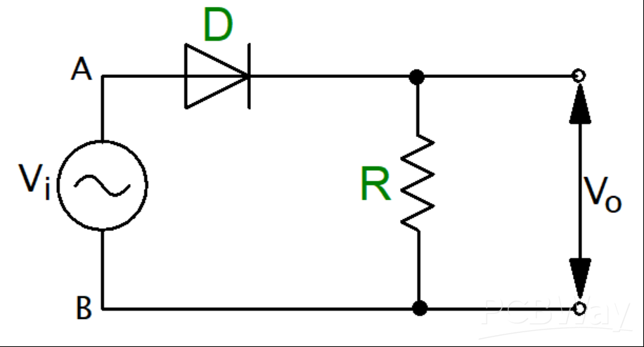
Figure 1:Negative Clipper Circuit
The Input Positive Cycle
On applying an input voltage to the circuit, the input positive cycle turns the circuit’s point A positive compared to point B. The result is that the diode is forward-biased and thus operates like a closed switch. This makes the whole input voltage appear across the circuit’s load resistor R and produce an output, Vo.
The Input Negative Cycle
On the negative half cycle at the input, point A of the circuit goes negative compared to point B and the resultant effect is that the diode becomes reverse-biased, acting like an open electric switch. The voltage across the load resistance becomes zero giving an output voltage, Vo, as zero.
The Negative Series Clipper Waveforms

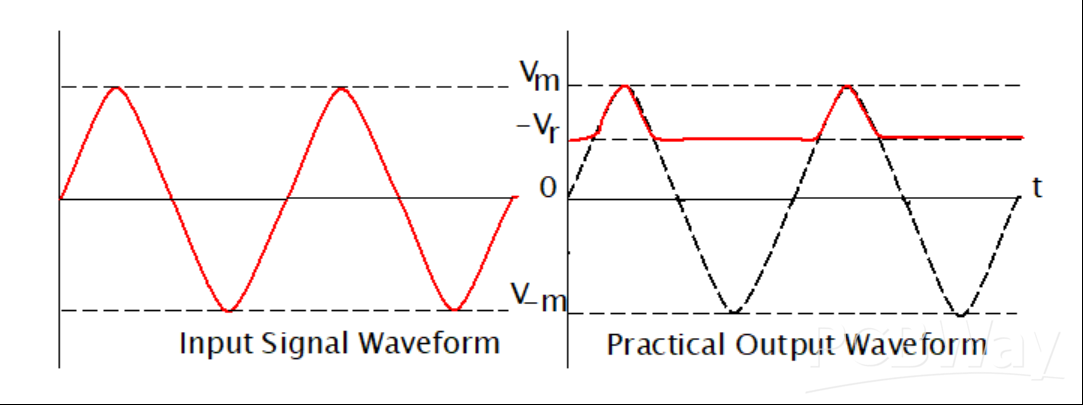
Figure 2:Negative Series Clipper Waveforms
Observing the waveforms drawn, we can only note that the negative portion of the peak of the waveform was clipped. This action is caused by the passing of voltage VO across the load resistor R. From the figures; we can notice that a bit of the negative cycle remains in the practical waveform, which is an effect caused by the conduction voltage of the diode. The diode conduction voltage is rated at 0.7V. The conduction voltage causes the difference observed between the ideal and the practical waveforms.
Here the diode is connected in series with the resistance of the load. Then it is biased using a positive reference voltage Vr, whose purpose is to attenuate the waveform’s negative portion.
Below is the figure for the negative series clipper with a positive reference voltage, Vr
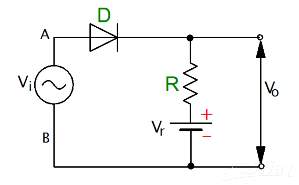
Figure 3:Negative series clipper with a positive reference voltage, Vr Circuit Diagram
During the positive input cycle, the diode goes into conduction mode when the voltage at the anode exceeds the voltage at the cathode of the circuit diode. The cathode voltage remains equal to the reference voltage, and the output waveforms are shown below.
Here, the diode is connected in series with the circuit’s input signal, and the biasing is achieved using the negative reference voltage to attenuate the waveform’s negative portion. The circuit connection is done as shown in the figure below.
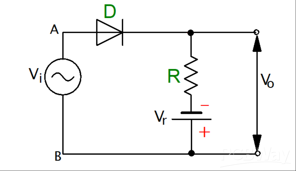
Figure 4:Negative series clipper with a negative reference voltage, Vr Circuit Diagram
A positive half cycle occurs after applying a positive voltage on the circuit. During this positive half cycle, the circuit diode becomes forward-biased, and the same voltage at the input appears at the circuit’s output. On the other hand, in the negative half cycle, the circuit diode becomes reverse-biased, and hence conduction does not occur. On the production, we shall have the reference voltage as the only display; hence the clipping of the negative cycle occurs immediately after the given reference voltage.
The figure below displays the waveforms diagram.
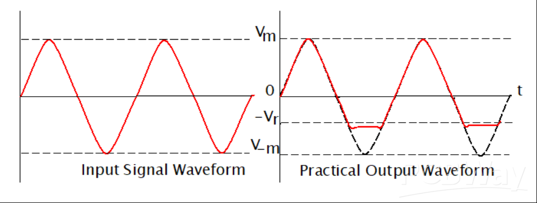
Figure 5:Negative series clipper with a negative reference voltage, Vr Waveforms
This is a clipper circuit where the diode is connected parallel with the circuit’s input signal, and it attenuates the negative waveform portion. The figure below represents the negative parallel/ shunt clipper.
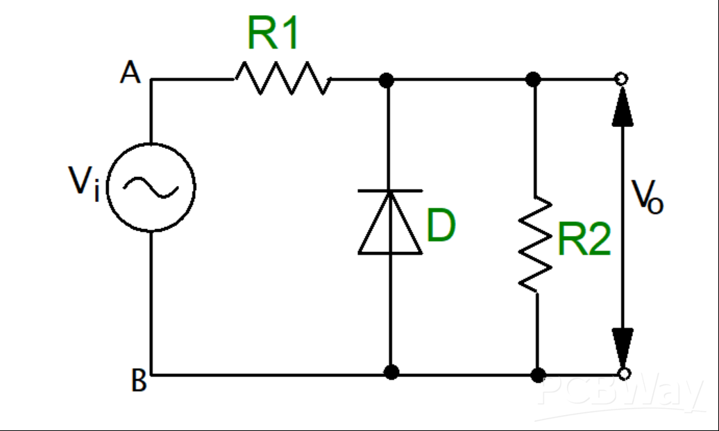
Figure 6:Negative Parallel Clipper Circuit Diagram
Input Positive Cycle
Applying the input voltage, the input positive cycle makes the circuit’s point A positive compared to point B. The action reverse-biases the diode and makes it behave like an open electric switch. The voltage across the load resistor equals the voltage at the input. Therefore, Vi is equal to Vo.
Input Negative Cycle
For the negative cycle input, point A becomes negative compared to point B. The action forward biases the diode making it behave like a closed electric switch. The voltage across the resistor becomes zero since we have zero current flow.
Waveforms
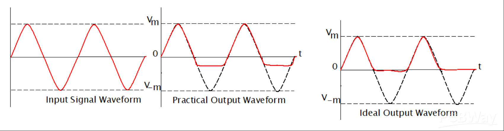
Figure 7:Negative Parallel Clipper Waveforms
From the waveforms, we can see that only the negative peak portion of the waveform was clipped. The action is caused by the voltage that goes across.
This is a combination of both the negative and the positive clipper circuits. These circuits are also known as combinational circuits.
The circuit and waveforms are shown in the figure below.
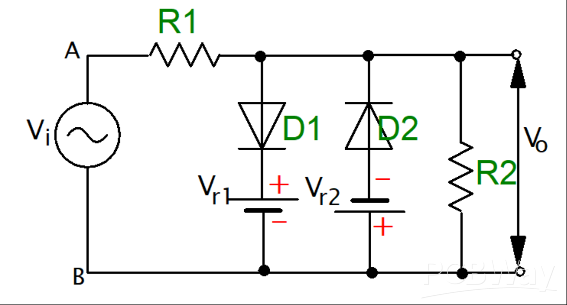
Figure 8:The Two-Way Clipper Circuit Diagram
The waveform for the two-way clipper is shown below.
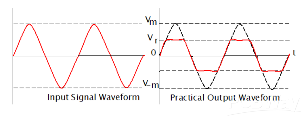
Figure 9:The Two-Way Clipper Circuit Waveforms
The article has introduced negative clipper circuits and summarized some of their types as listed below:
· Negative series clipper
· Negative series clipper with a negative reference voltage, Vr
· Negative series clipper with a positive reference voltage, Vr
· Negative parallel clippers
At the end of the article, we have introduced a combination of positive and negative clipper circuits, which are very beneficial in power electronics. The idea is to help engineers and technicians to know how to filter unwanted distortions from electric circuits.


