


|
|
Arduino_Nano_v3.x |
x 1 | |
|
|
16x4 LCD Display |
x 1 | |
|
|
button |
x 1 | |
|
|
BME280 sensor board |
x 1 |

|
Soldering iron |
|

|
Soldering Iron Wire Welding Lead Roll |
Arduino Barometer + Barograph with BME280 Sensor
A barograph is a barometer that records the barometric pressure over time in graphical form. This instrument is also used to make a continuous recording of atmospheric pressure.
The former Barographs use the pressure-sensitive element, which is linked to a pen arm in such a way that the vertical displacement of the pen is proportional to the changes in the atmospheric pressure. This pen marks pressure changes on specially marked paper that is placed on a disc that rotates 360 degrees over 24 hours. In the picture below you can see what a Barograph from the last century looks like.

The barometer and the barograph are basic local instruments (independent of the Internet) in Meteorology that serve to predict the weather. This time I will present you a very simple way, using an Arduino microcontroller, you can make an electronic Barometer + Barograph that presents the results in graphic form on a 20x4 LCD display. The basic project is taken from "cxem.net" by the author AMatroskin, in which I modified and now the pressure is displayed in hPa instead of mmHg, and what is much more important, instead of the Absolute, the Relative Atmospheric Pressure for the specific altitude is displayed, which is a common standard in Meteorology.
For this purpose we need to enter the Relative Standard Atmospheric Pressure for the current altitude (As described further in the text), in the line:
#define SEALEVELPRESSURE_HPA (932.17) // for Ohrid, 698m altitude
and we can calculate that, on one of the online calculators, such as:
https://www.mide.com/air-pressure-at-altitude-calculator
Also further down the line
value = round ((bme.seaLevelForAltitude(698, bme.readPressure())/100))
the current altitude in meters should be entered.

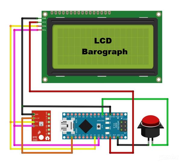
As I mentioned before, the device is very simple to build and contains only a few components:
- Arduino Nano microcontroller
- 20x4 I2C protocol LCD Display
- BME 280 Pressure sensor board
- and one Button
Now let's see how the device works in reality. First of all, it takes 24 hours to draw a complete graph. The display shows the current Relative Atmospheric Pressure, as well as the positive or negative difference in hectopascals, for a given previous time period. This period can be 3,6,12, and 24 hours. Correct interpretation of this difference is the basis for accurate weather prediction. And now a few words about the graph. The maximum number of values on the vertical axis can be 28 (7vertical dots on every of four rows). At the beginning of the code, the range in which the air pressure is read can be changed, i.e. the smallest and the largest value. Depending on these values, the resolution of the graph also changes. For example, if we choose the difference between the minimum and maximum pressure to be 28, then 1 Hectopascal corresponds to one line on the Y axis of the graph. The sixteen values on the X axis represent time, and here the resolution depends on the selected elapsed time value.
Basically, when the pressure rises, an improvement in the weather is expected, and conversely, when it decreases, a worsening of the weather is expected.

And finally, the device is placed in a suitable box made of PVC material with a thickness of 5 mm, and covered with self-adhesive colored wallpaper. Let me mention that the BME280 sensor is placed inside the box, because in this case we measure only the pressure, which is independent of the temperature .
/*
Barometer with digital and graphic display of atmospheric pressure data.
Components: Screen text LCD 2004, platform: arduinio nano/uno (Atmega328 or more), pressure sensor: BME 280.
Amatroskin 2022.
*/

#include <LiquidCrystal_I2C.h>
#include <Wire.h>
#include "GyverButton.h"
#include <Adafruit_Sensor.h>
#include <Adafruit_BME280.h>

#define SEALEVELPRESSURE_HPA (933,17)       // Set the height
#define BTN_PIN 3                            //Button Pin
#define BASE_PERIOD 675000                   //Main array acquisition period 675000ms = 11.25 min (*16 bars = 3 hours) maximum graph resolution
#define MIN_VAL 990                          //The minimum value displayed on the chart
#define MAX_VAL 1035                          //The maximum value displayed on the graph
LiquidCrystal_I2C lcd(0x27, 20, 4);          //We create the necessary objects
GButton butt1(BTN_PIN);
Adafruit_BME280 bme;

uint32_t tmr1, tmr2;                          //timer variables
uint32_t  set_period = BASE_PERIOD;           //Display period, changes in multiples of 3 hours (3, 6, 12, 24)
int16_t plot_array[20];                       //Data array for drawing a chart
uint16_t base_array [128];                    //The base array stores all measurements for the last 24 hours (128 cells * 11.25 minutes = 1440 minutes = 24 hours)
int16_t value, delta;                         //Current (taken) readings, difference in readings for a selected period of time
byte interval = 1;                            //Interval displayed on the screen (time difference between adjacent chart bars)
                                              // 11.25 min * 16 = 3 hours, 22.5 min - 6 hours, 45 min - 12 hours, 90 min - 24 hours
void setup() {
  read_all ();
  //  Serial.begin(9600);
  attachInterrupt(1, isr, CHANGE);
  butt1.setDebounce(80);                      // anti-bounce setting (default 80 ms)
  butt1.setTimeout(300);                      // hold timeout setting (default 500ms)
  lcd.init();
  lcd.backlight();
  lcd.clear();
  if (!bme.begin(0x76)) {                              //Initialization of the BME280 sensor at address 0x76 (default)
    //Serial.println("Could not find a valid BME280!");//Printing an Error Message to the Port Monitor
    lcd.setCursor(3, 1);
    lcd.print(F("No connection"));                     //___________________________or on the screen
    lcd.setCursor(5, 2);
    lcd.print(F("to sensor"));
    while (1);                                          //won't go without a sensor.
  }

  if (!digitalRead(BTN_PIN)) {                          //Reset settings when turned on with the button held down
    for (byte i = 0; i < 128; i++) base_array [i] = 0;  //Erase data
    update_all ();                                      //Save
    lcd.setCursor(5, 1);                                //Report it
    lcd.print(F("Reset data"));
    lcd.setCursor(9, 2);
    lcd.print(F("OK"));
  }
  while (!digitalRead(BTN_PIN));
  lcd.clear();

  initPlot();                                           //Initializing Symbols for Rendering

  value = round ((bme.seaLevelForAltitude(700, bme.readPressure())/100));//We take the current readings, convert to mm Hg.
  base_array[0] = value;
  get_data ();
}

void isr() {                                              //We poll the button in the interrupt to catch the click anyway
   butt1.tick();
}

void loop() {
  butt1.tick();                                           //Poll button
  if (butt1.isClick()) {                                  //When you press:
    interval *= 2;                                        //Switching the chart scale
    if (interval > 8) interval = 1;
    set_period = BASE_PERIOD * interval;                  //Recalculate the interval for updating data from the sensor
    get_data ();                                          //Update information on the display
  }

  if (millis() - tmr1 >= BASE_PERIOD) {                   //We collect the basic array of data
    tmr1 = millis();                                      //Every 11.25 minutes we take readings from the sensor
    for (int i = 126; i >= 0; i--) {                      //Shift the entire array by one point
      base_array[i + 1] = base_array[i];
    }
    value = round ((bme.seaLevelForAltitude(700, bme.readPressure())/100));//Convert to mm/Hg.
    base_array[0] = value;                                 //Write the latest readings to an array
    update_all ();                                         //And remember in EEPROM
  }

  if (millis() - tmr2 >= set_period) {                     //After a period of time set_period (milliseconds)
    tmr2 = millis();                                       //Refreshing the data on the screen
    get_data ();
  }
}

void get_data () {                                          //We draw 16 columns of the diagram on the screen
  for (int i = 15; i >= 0; i--) {
    drawPlot(0, 3, 16, 4, MIN_VAL, MAX_VAL, (base_array[i * interval]));
  }
  delta = ((base_array[0]) - (base_array[15 * interval]));  //We calculate the delta (pressure change) for the selected interval
  screen_data (value, delta, (interval * 3));               //Displaying text information on the screen
}

void screen_data (int value, int delta, byte interval) {    //The function of displaying text information on the screen (everything except for the chart bars)
  lcd.setCursor(16, 0);
  lcd.print(value);
  lcd.setCursor(17, 2);
  if (delta == value) delta = 0;
  if (delta > 0) {
    lcd.print("+");
  } else if (delta < 0) {
    lcd.print("-");
  } else if (delta == 0) {
    lcd.print(" ");
  }
  lcd.setCursor(18, 2);
  lcd.print(abs(delta));
  if (abs(delta) < 10) {
    lcd.setCursor(19, 2);
    lcd.print(" ");
  }
  lcd.setCursor(17, 1);
  lcd.print("hPa");
  lcd.setCursor(17, 3);
  lcd.print(interval);
  (interval < 10) ? lcd.print("h ") : lcd.print("h");
}

void initPlot() {
  // necessary symbols for work
  // created in http://maxpromer.github.io/LCD-Character-Creator/
  byte row8[8] = {0b11111,  0b11111,  0b11111,  0b11111,  0b11111,  0b11111,  0b11111,  0b11111};
  byte row7[8] = {0b00000,  0b11111,  0b11111,  0b11111,  0b11111,  0b11111,  0b11111,  0b11111};
  byte row6[8] = {0b00000,  0b00000,  0b11111,  0b11111,  0b11111,  0b11111,  0b11111,  0b11111};
  byte row5[8] = {0b00000,  0b00000,  0b00000,  0b11111,  0b11111,  0b11111,  0b11111,  0b11111};
  byte row4[8] = {0b00000,  0b00000,  0b00000,  0b00000,  0b11111,  0b11111,  0b11111,  0b11111};
  byte row3[8] = {0b00000,  0b00000,  0b00000,  0b00000,  0b00000,  0b11111,  0b11111,  0b11111};
  byte row2[8] = {0b00000,  0b00000,  0b00000,  0b00000,  0b00000,  0b00000,  0b11111,  0b11111};
  byte row1[8] = {0b00000,  0b00000,  0b00000,  0b00000,  0b00000,  0b00000,  0b00000,  0b11111};
  lcd.createChar(0, row8);
  lcd.createChar(1, row1);
  lcd.createChar(2, row2);
  lcd.createChar(3, row3);
  lcd.createChar(4, row4);
  lcd.createChar(5, row5);
  lcd.createChar(6, row6);
  lcd.createChar(7, row7);
}

                                              //Diagram drawing, code taken from Guyver https://alexgyver.ru/lcd-plots-and-bars/
void drawPlot(byte pos, byte row, byte width, byte height, int min_val, int max_val, int fill_val) {

  for (byte i = 0; i < width; i++) {
    plot_array[i] = plot_array[i + 1];
  }
  fill_val = constrain(fill_val, min_val, max_val);
  plot_array[width - 1] = fill_val;
  for (byte i = 0; i < width; i++) {         // each parameter column
    int infill, fract;

                                             // find the number of whole blocks, taking into account the minimum and maximum, to display on the chart
    infill = floor((float)(plot_array[i] - min_val) / (max_val - min_val) * height * 10);
    fract = (infill % 10) * 8 / 10;                          // find the number of remaining stripes
    infill = infill / 10;
    for (byte n = 0; n < height; n++) {     // for all graph lines
      if (n < infill && infill > 0) {       // while we're below the level
        lcd.setCursor(i, (row - n));        // fill in cells
        lcd.write(0);
      }
      if (n >= infill) {                          // if you reach the level
        lcd.setCursor(i, (row - n));
        if (fract > 0) lcd.write(fract);          // заполняем дробные ячейки
        else lcd.write(16);                       // if fractional == 0, fill empty
        for (byte k = n + 1; k < height; k++) {   // everything that is on top is filled with empty
          lcd.setCursor(i, (row - k));
          lcd.write(16);
        }
        break;
      }
    }
  }
}

void update_all () {                             //Обновляем данные в EEPROM
  eeprom_update_block((void*)&base_array, 0, sizeof(base_array));
}

void read_all () {                              //Reading data from EEPROM
  eeprom_read_block((void*)&base_array, 0, sizeof(base_array));
}
Arduino Barometer + Barograph with BME280 Sensor


- Comments(0)
- Likes(0)
More by Mirko Pavleski
-
 How to make simplest possible autorange Capacitance meter
The capacity measurement option is usually only available in more expensive multimeters, so it is d...
How to make simplest possible autorange Capacitance meter
The capacity measurement option is usually only available in more expensive multimeters, so it is d...
-
 How to turn mini Tesla Coil from Aliexpress into a Real Powerful SSTC with big spark
Some time ago I bought a mini tesla coil kit from an online store that cost less than $4. It's a ve...
How to turn mini Tesla Coil from Aliexpress into a Real Powerful SSTC with big spark
Some time ago I bought a mini tesla coil kit from an online store that cost less than $4. It's a ve...
-
 DIY Arduino ultrasonic Sonar - Radar on TFT display
Ultrasonic sonar is devices that use sound waves with frequencies higher than the upper audible lim...
DIY Arduino ultrasonic Sonar - Radar on TFT display
Ultrasonic sonar is devices that use sound waves with frequencies higher than the upper audible lim...
-
 Simple ESP32 Internet radio on VFD Display
Internet radio, also known as online radio or streaming radio, refers to the broadcasting of audio ...
Simple ESP32 Internet radio on VFD Display
Internet radio, also known as online radio or streaming radio, refers to the broadcasting of audio ...
-
 Short review of small music Tesla Coil with Bluetooth
A Solid State Tesla Coil (SSTC) is a type of Tesla coil that uses solid-state electronic components...
Short review of small music Tesla Coil with Bluetooth
A Solid State Tesla Coil (SSTC) is a type of Tesla coil that uses solid-state electronic components...
-
 Testing 2500W Large Induction Heater
An induction heater is a device that uses electromagnetic induction to heat objects. It consists of...
Testing 2500W Large Induction Heater
An induction heater is a device that uses electromagnetic induction to heat objects. It consists of...
-
 Arduino FFT Audio Spectrum analyzer on 8x32 color matrix WS2812B
The spectrum analyzer displays the amplitude of signals as a function of frequency, allowing engine...
Arduino FFT Audio Spectrum analyzer on 8x32 color matrix WS2812B
The spectrum analyzer displays the amplitude of signals as a function of frequency, allowing engine...
-
 Unusual Led Ring Arduino Clock, Temperature, and Humidity meter
There are many arduino clock projects with temperature and humidity readings where the results are ...
Unusual Led Ring Arduino Clock, Temperature, and Humidity meter
There are many arduino clock projects with temperature and humidity readings where the results are ...
-
 How to make simple portable PEMF Magnetic Pulser
PEMF (Pulsed Electromagnetic Field Therapy), which is also known as magnetic pulse therapy uses ele...
How to make simple portable PEMF Magnetic Pulser
PEMF (Pulsed Electromagnetic Field Therapy), which is also known as magnetic pulse therapy uses ele...
-
 Single Mosfet Mini SSTC Tesla coil with 10 + cm Spark
A Solid State Tesla Coil (SSTC) is a type of Tesla coil that uses solid-state components such as tr...
Single Mosfet Mini SSTC Tesla coil with 10 + cm Spark
A Solid State Tesla Coil (SSTC) is a type of Tesla coil that uses solid-state components such as tr...
-
 How to Make EM84 (6E2) Vacuum Tube Stereo VU Meter
A VU meter, also known as a Volume Unit meter, is a device used to display the audio signal level ...
How to Make EM84 (6E2) Vacuum Tube Stereo VU Meter
A VU meter, also known as a Volume Unit meter, is a device used to display the audio signal level ...
-
 Universal Arduino Staccato controller for SSTC and VTCC Tesla Coils
The VTTC Staccato Controller was developed in the attempt to create longer sparks from VTTCs while ...
Universal Arduino Staccato controller for SSTC and VTCC Tesla Coils
The VTTC Staccato Controller was developed in the attempt to create longer sparks from VTTCs while ...
-
 DIY extremly Sensitive and cheap Arduino Seismometer
A seismometer, is an instrument used to detect and record ground motion caused by seismic waves, su...
DIY extremly Sensitive and cheap Arduino Seismometer
A seismometer, is an instrument used to detect and record ground motion caused by seismic waves, su...
-
 DIY Extremly Sensitive and cheap Geophone sensor for Earthquakes detecting
A geophone is a device used in geophysics to detect ground movement. It is specifically designed to...
DIY Extremly Sensitive and cheap Geophone sensor for Earthquakes detecting
A geophone is a device used in geophysics to detect ground movement. It is specifically designed to...
-
 Arduino FFT Spectrum analyzer on VFD display GP1287
An audio spectrum analyzer is a device that visualizes the frequency content of an audio signal. It...
Arduino FFT Spectrum analyzer on VFD display GP1287
An audio spectrum analyzer is a device that visualizes the frequency content of an audio signal. It...
-
 DIY simple Spark Gap Tesla Coil
Tesla coil is a type of resonant transformer circuit invented by Nikola Tesla around 1891. It is a ...
DIY simple Spark Gap Tesla Coil
Tesla coil is a type of resonant transformer circuit invented by Nikola Tesla around 1891. It is a ...
-
 DIY PC controlled high power PEMF Therapy Device
PEMF or Pulsed Electromagnetic Field therapy is a type of therapy that uses electromagnetic fields ...
DIY PC controlled high power PEMF Therapy Device
PEMF or Pulsed Electromagnetic Field therapy is a type of therapy that uses electromagnetic fields ...
-
 DIY Precise Arduino Miliohmmeter
In practice, we very often need to measure low resistances. Measuring low-value resistances, especi...
DIY Precise Arduino Miliohmmeter
In practice, we very often need to measure low resistances. Measuring low-value resistances, especi...
-
Creative Micro Designs Inc. CMD FD-2000 / FD-4000 3D Printable Case
92 0 0 -
Creative Micro Designs Inc. CMD FD-2000 / FD-4000 Metal Case
115 0 0 -
-
-
IoT Indoor system with ESP32 to monitor Temperature, Humidity, Pressure, and Air Quality
674 0 3 -
Naruto Multi-color PCB printed with UV technology
232 2 1 -
-


