By Hesam Moshiri, Anson Bao
The high temperature of the power components is a known phenomenon in electronics. To overcome this challenge, the designers mount heatsinks on the components to dissipate the heat, however, in many commercial and home appliance devices, the embedded heatsink is not adequate and the air must be circulated faster to reduce the heatsink and component temperature, otherwise, the lifetime of the component is reduced significantly.
The proposed automatic FAN controller board is simple, compact, and can be embedded inside commercial devices. The LM35 temperature sensor could be fixed on the heatsink using some silicon glue.
The user can easily set the temperature threshold using a potentiometer. The board can be supplied using a 5V or a 12V supply, therefore a variety of 5V, 12V, miniature, and PC FANs can be used.
I used Altium Designer 21 and SamacSys component libraries (SamacSys Altium plugin) to draw the schematic and PCB. Except for the connectors, all components are SMD and easy to solder.
• Download the Gerbers or order 10 high-quality PCBs for just 5.0USD
• To order a fully assembled PCB board (plus FREE shipping).
Circuit Analysis
Figure 1 shows the schematic diagram of the device. The two major components are a temperature sensor and an OPAMP.
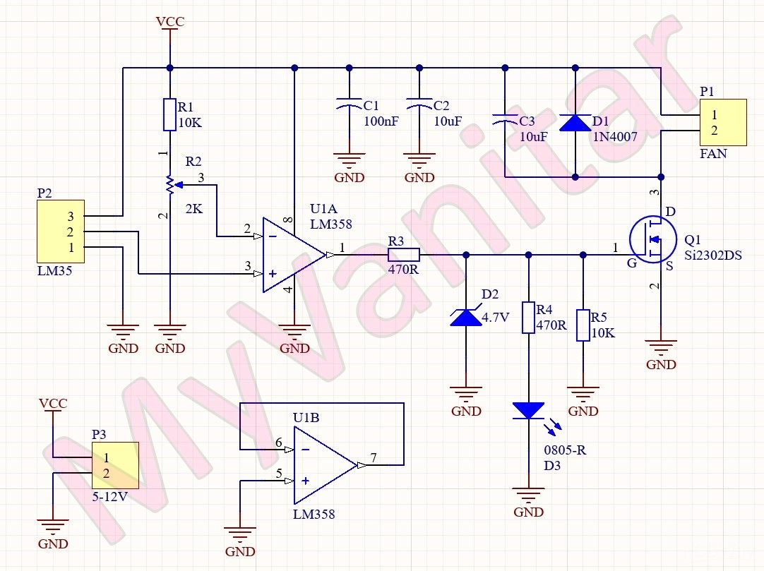
Figure 1
The schematic diagram of the cooling Fan controller (Altium Designer)
U1 is the LM358 opamp [1] that is configured as a comparator. If the voltage of the positive input is higher/lower than the negative input, then the output would be close to the VCC/GND. When the temperature of the environment (the voltage on the positive pin) is higher than the pre-set temperature (the voltage on the negative pin), then the output will be activated and vice versa. The LM358 has two opamps. The second opamp is not used and configured as a voltage follower. R2 is a multiturn potentiometer to easily adjust the temperature threshold.
R3 and D2 are used to limit the output voltage of the U1 because the maximum tolerable voltage of the gate pin of Q1 is 8V [2], moreover, they help to maintain the voltage of the D3 LED at around 4.7V, so the value of the R4 is fixed to 470R for any supply voltage. R5 is used to prevent the unwanted triggering of the Q1 gate.
Q1 is the SI2302 N-Channel SMD Mosfet [2] that can switch up to 2.2A continuously, so I decided to use this MOSFET, instead of using a mechanical relay. D1 protects the Q1 against reverse inductive currents and C3 is used to reduce the switching noises. C1 and C2 are bypass capacitors and are used to reduce noises.
PCB Layout
Figure 2 shows the PCB layout of the design. It is a two layers PCB board and except for the connectors, all components are SMD. The board size is 3.8cm*1.9cm.

Figure 2
The PCB layout of the cooling fan controller (Altium Designer)
When I decided to design the schematic and PCB for this project, I realized that I don’t have the component libraries of U1[3] and Q1[4] in my component libraries storage. So as usual, I selected IPC-rated SamacSys component libraries and install the missing libraries (schematic symbol, PCB footprint, 3D model) using the free SamacSys tools and services. There are two methods to import the libraries into the electronic designing CAD software: you can visit the componentsearchengine.com and download and import the libraries, or you can use the SamacSys CAD plugins and directly import the component models into the design environment. Figure 3 shows all supported electronic designing CAD software [5]. As it is clear, all known CAD Software is supported. I use Altium Designer, so I installed the missing libraries using the SamacSys Altium plugin (Figure 6) [6].

Figure 3
All supported electronic designing CAD software by the SamacSys plugins
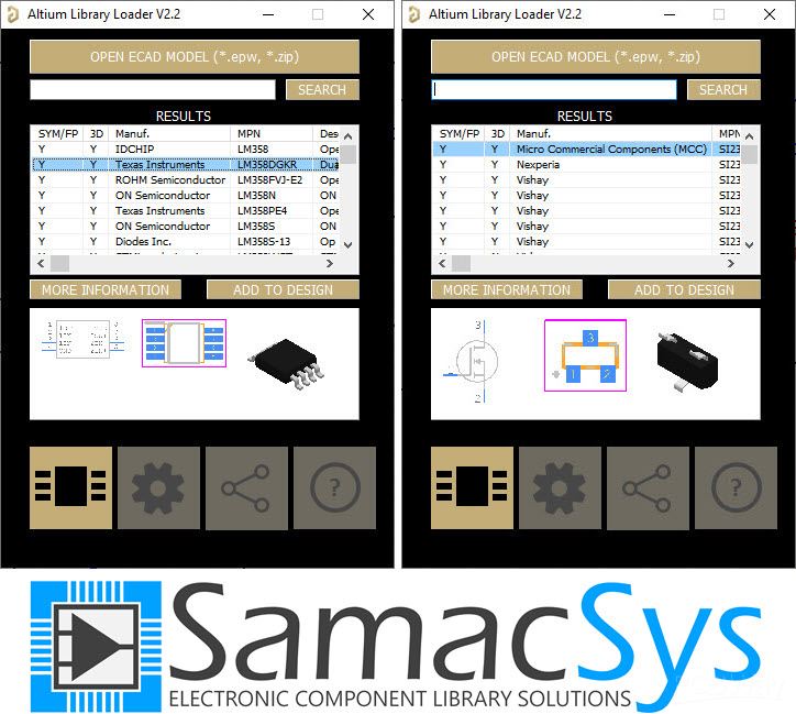
Figure 4
Selected component libraries in the SamacSys Altium plugin
Bill of Materials
Figure 5 shows the bill of materials for the project.
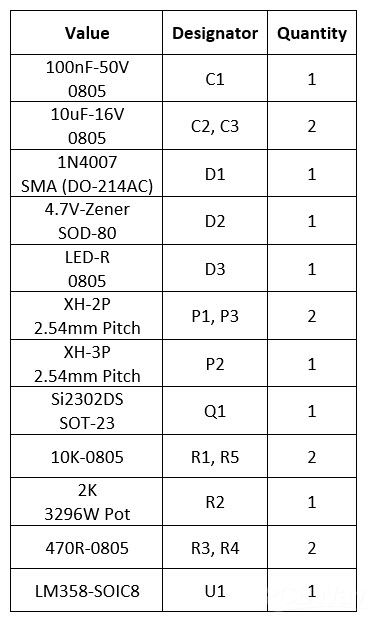
Figure 5
Bill of materials
References
[1]: LM358 datasheet: https://www.st.com/resource/en/datasheet/lm358.pdf
[2]: SI2302 datasheet: https://www.vishay.com/docs/63653/si2302dds.pdf
[3]: LM358 schematic symbol, pcb footprint, 3D model: https://componentsearchengine.com/part-view/LM358D/STMicroelectronics
[4]: Si2302 schematic symbol, pcb footprint, 3D model: https://componentsearchengine.com/part-view/SI2302DDS-T1-GE3/Vishay
[5]: Electronic designing CAD software plugins: https://www.samacsys.com/library-loader-help
[6]: Altium Designer plugin: https://www.samacsys.com/altium-designer-library-instructions


